Filter Tuning with Brian White’s PID Toolbox
The filter tuning method introduced in this article uses the PID Toolbox (PTB) to analyze blackbox data. This method is a lot more sophisticated rather than playing around with sliders until the motors get hot. It still is quick, easy and accurate. This filter tuning article is based on many discussions with Brian White himself, the developer of PTB, who I want to thank for sharing his knowledge. For the ones, that do not want to know the details and just want good filters fast, skip this article and go straight ahead to the fast lane article.
Filter tuning is the prerequisite for PID Tuning. Without properly set filters, the unfiltered noise will have an impact on the PID Loop. Therefore, noise prevents finding a good tune. We use PID Toolbox (PTB). A handy tool to visualize the noise with the Spectral Analyzer (SA) and the Step Response Tool (SR), among other features. We also use the PTB for Brian White’s 2 Step Basement Tuning for fast and easy PID tuning.
Be aware, that noise can be filtered, but it still is there, shaking your quad. So, be sure to have a clean build, especially if you want to make videos. Potentially, noise will not just make it through to your PID loop, but will also be visible in your footage. Also take care of electronically induced noise. Use a good capacitor, keep high voltage cables as far as possible from the flight controller and use shielding when needed.
Have a clean build
Therefore, before the filters are tuned, get your setup right. Some of the noise can mutually be prevented when using high quality components. Also, take care that your build is neatly put together. That means to ty down everything that your eventually cause vibrations like loose cables, or components banging against each other. Also, Antennas or Camera mounts should not wobble around too much. When you can hear something clatter around, you will see it as noise in the spectral analyzer. Take care your flight controller has some memory for the log, or another way to store the data. We recommend using Betaflight as flight controller firmware. But it will work with other firmware that can generate blackbox logfiles as well.
Create a good log for filter tuning
We now generate good log data that allows an analysis in the next step. Therefore we set the debug mode to gyro_scaled and the log rate to 2khz.
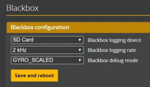
Betaflight BlackBox Debug Mode Gyro Scaled
CLI Commands:
set blackbox_p_ratio = 64
set debug_mode = GYRO_SCALED
For the analyzes we need the pre-filtered gyro signal. Filter settings do not interest us a this point. They the don’t have an influence on the analysis. However, if PIDs and filters are set completely wrong, you may burn your motors/ESC or crash. The Betaflight defaults will very likely work fine for the test-flight. Therefore, it is recommended to reset the PID and filter settings to default, but it is not required.
Unfortunately, unlike the basement tuning, this part cannot be done safely in the basement. We need to go out in the field and to several throttle sweeps. A throttle sweep means to go all the way through the throttle band. This means, from hovering slowly (at least 3 seconds) increasing up to 100% throttle in a straight forward flight. Do this several times (at least 3 times). Prevent any moves and do not provoke propwash. But don’t worry too much if there is. We can later select the timeframe witch good data for the analysis and remove the not so good parts. Just make sure, you have at least three good throttle sweeps in a row.
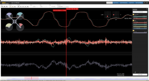
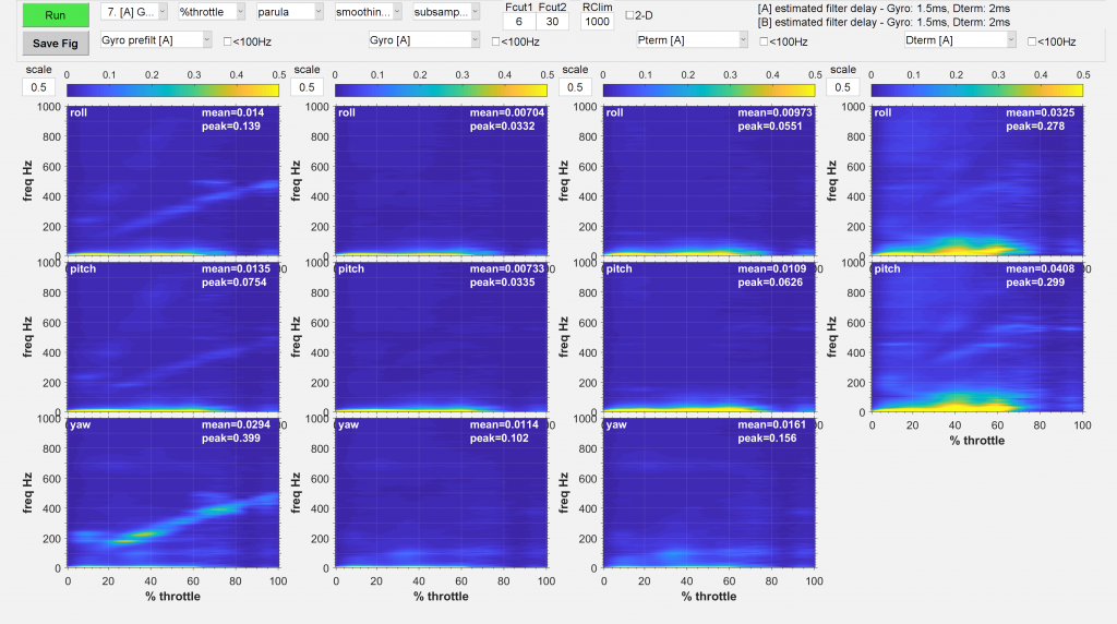
PID Toolbox Spectral Analyzer
We now load the just created log with the throttle sweeps into the PID Toolbox. If you are not familiar with PID Toolbox check out this Video where Brian explains how to use it. After „Load+Run“ the file we can set the start and end time of the timeframe we actually want to analyze. Press the „Spectral Analyzer“ button to open the SA Window.
Choose Number 7 or 8 ([A] Gyro Prefilt) from the presets menu and hit „Run“. I personally recommend to display the graph in „parula“. But use what you prefer. Just use the same to be able to compare it with your other analysis.
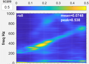
PID Toolbox Spectral Analyzer Prefiltered Noise Pattern
What to look for
We now look for two things: the „Estimated filter delay“ and „noise“. If we don’t see a filter delay, the correct debug mode was not set, or the log is not appropriate.
Filter Delay
The target is a balance between filter latency and a clean noise profile. A filter latency of <1.5ms Gyro and <2.5ms D Term should be targeted. Just to be exact, the filter latency numbers displayed in the spectral analyzer are displayed without the internal gyro lowpass filter (lpf) latency. The actual latency adds another Millisecond for the internal lpf which is built into the gyro.
Filter delay increases the time the PID-loop can react on changes. Is the delay too high, the reaction comes too slow, actually leading to an inappropriate reaction. This in combination with a hight D can cause low frequency noise (< 100HZ). Therefore, to get rid of low frequency noise the latency, which causes phase delay, should be as low as possible. As low as the noise profile allows.
It is important to know: high latency causes low frequency noise. Low frequency noise (< 100HZ) cannot und must not be filtered! Filtering below 100HZ will have a negative effect on flight performance. Also, it will further increase latency, making the noise even worse. To reduce low frequency noise, decrease filtering and/or PD Gain. PD Gain will decrease D, without changing the PD Balance. Check out Brian’s Video on that matter, if you are interested in the background.
Be aware, that the filter delay cannot be calculated from throttle sweeps or the basement tuning logs. You will have to create a separate log with some moves for a reliable filter latency calculation. The throttle sweep log is not suitable for that. Just do basement tuning maneuvers and you have a suitable log within 20s. With that log the estimation is most accurate. Use a higher lograte for better resolution (2k 0,25, 4K 0,125). It’s still an estimate. So don’t be surprised if it varies +/- 0,5 from flight to flight.
Noise
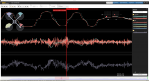
First, let’s talk about what „noise“ ist. When we talk about noise in this context, we mean occurrences of certain frequencies. We see them in yellow color in the spectral analyzer graph (depending in the chosen color schema). It’s a simplified term and not always scientifically correct.
There are several types of noise, each with a distinct pattern. Depending on the noise pattern, we choose the suitable filter.
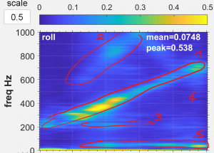
PID Toolbox Spectral Analyzer Prefiltered Noise Pattern marked
- Motor noise
- Motor harmonics
- Noise band(s)
- Diffuse „background“ noise
- Low frequency oscillations
Motor Noise
The motor noise (1) changes frequency with throttle. An increase in throttle increases the frequency of the noise. Motor harmonics (2) correlate with the motor noise itself and therefore have a similar pattern, just at a higher frequency and lower amplitude.
The motor noise and harmonics are best fought with the RPM filter. Bidirectional DShot is required for that. And make sure, the motor pole number is set correctly in the config tab. If bidirectional DShot not an option, the dynamic notch is used to dampen motor noise, but a lot less efficient. If RPM filtering is active, the dynamic notch can be used otherwise, which brings some advantages.
Noise Bands
A noise band (3) is independent of motor rpm and throttle. It is shown as a straight line (independent of throttle), or as a blob, when it is triggered at certain motor rpm range. What happens is, that the energy from vibrations is absorbed and given off at a characteristic frequency. Frame resonance is a typical example. A frame has characteristic noise bands, depending on size, material and form. Noise bands are best dampened with a notch filter.
Noise bands below 100hz cannot and must not be filtered. They have a different source, such as too much noise in combination with too high D and/or too much filter latency (too much filtering).
However, noise bands also come from loose screws, clattering cables or even from electronically induced noise. So, always check out the hardware, before tuning filters.
Diffuse background Noise
Diffuse background noise (4) does not really have a clear pattern. It’s like more of a shade or some faint blobs all over the place. It’s best filtered with a lowpass filter.
How to fight noise
Despite from noise-prevention we have several filter types to take care of the noise. First, let’s talk about the filter types real quick.
Hardware Gyro Filter
It’s just mentioned for completeness. The gyro already has a built-in hardware lowpass filter which already dampens most of the unwanted frequencies. It’s fast, but still has about 1ms filtering latency, out of the box. This latency has to be added to the overall filter latency. The numbers displayed in the PTB spectral analyzer can only calculate the software filters.
Lowpass Filters
The lowpass filter just dampens the noise starting at the cutoff frequency. The further away (the higher the frequency) the noise is from the cutoff frequency, the more it is dampened. So, lpf do not have a „hard“ cutoff at the given frequency. It starts weak and gets stronger the further away from the cutoff. The PT1 are weaker, simply spoken, but a lot faster. BQ are stronger, but create more latency.
Also lowpass filters can be dynamic. The difference to a static lowpass is, that if no noise is detected, the cutoff frequency is increased automatically to reduce latency. However, the benefit is marginal as the detection also required resources.
The opposite would be a highpass filter, letting higher frequencies through and dampening lower frequencies. But that would not make a lot of sense. Because it’s the low frequencies (<100hz) that are the actual movement or shaking. That’s what we want to measure. Everything else is is just a byproduct of the way a gyro works.
Notch Filters
Notch filters dampen strongest at the center frequency and grow weaker towards at the cutoff frequency. The closer the center is to the cutoff frequency, the sharper and precise the notch filter is.
RPM Filters
RPM filters are a set of notch filters, that change dynamically with RPM (throttle). Therefore they need the RPM information for each motor from the ESC.
A specialty of RPM Filters is the harmonics. Normally, motor noise has harmonics with a distinct frequency correlating with the main frequency. The harmonics can be seen a several straight lines, like the main motor noise, but with lower amplitude.
So, the default RPM filters are actually a set of 12 notch filters for each axis: four motors times three harmonics. Multiplied by three axes makes 36 notches in sum.
How to set the filters
Now comes the easy part. We choose the suitable filter for the type of noise we see in the pre-filtered spectral analyzer graphs. How well the filters work, we see in the post-filtered spectral analyzer graphs. Because Gyro and D-term are filtered separately, we also distinguish between them in the analysis. For now, we focus on the pre-filtered noise to initially set the filters.
We always keep in mind, we want the least filtering (weak filters) possible for a minimum of latency. Still, the noise should be filtered well enough to prevent negative side effects. Especially D-Term is sensitive to noise, particularly if D is set high. Sometimes, the filters have to be retuned after PID tuning, when D exceeded a certain threshold. But be careful on changing filtering after tuning, as this will increase latency. Therefore it may cause more low frequency oscillations ending up ruining your tune.
What noise is too much noise
The question, what noise is good and what is too much cannot really be answered. But we can see it’s effect on the PID loop. Additionally, there is a certain correlation between D (especially D) and noise. The more D the copter requires, the less noise is acceptable. If the noise and D are too high, the result are hot motors up to flyaways. There is some tolerance, allowing to vary to the personal liking. So, I will not start a discussion, but rather give a personal opinion on that matter.
Samples of what can be considered too much
In following blackbox analyser graphs, the bottom trace is D term (blue). Top is gyro (green) and setpoint (red). Inbetween is PID sum, I, P and FF, just to see what term is dominating. The most important trace to look at, is the gyro trace (top) and D (bottom). In this series, a moderate amount of noise is let into the system. Then D is raised step by step.
Here we see moderate D term and gyro shaking. Up to that point, I’d personally consider noise and D low enough.
very low PD Oscillations
Next we see some oscillations, but only with some phantasy. The oscillations differ from shaking because they look more symmetric, less random. Also, we can start to see that the shaky PID sum has an effect on the gyro signal.
low PD Oscillations
In this graph the oscillations come obvious. But not only in the trace, they can be heard. Some refer to it as „thrilling“ noise. Either reduce noise or D to prevent hot motors and/or flyaways.
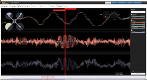
PD Oscillations
Finally a sample of an almost flyaway situation. This definitely is too much.
heavy PD Oscillations
How to fight motor noise
Motor noise is best filtered with RPM filters. Set the maximum and minimum according to where motor noise shows in the prefiltered spectral analyzer graph. The Q tells how sharp the filter is. A broader motor noise needs lower Q. A sharp motor noise can go with higher Q. Set the harmonics to the number visible in the graph. Take a close look, they may not be very strong.
RPM Q has to be set in the CLI. That’s different from the dynamic notch, which of course also has a Q Parameter. But dynamic notch Q can be set in die GUI. Take care not to mix them up.
Keep in mind, whenever the setup changes in matter of RPM min/max, for example other propeller angle, KV of the motors, throttle limits, this filter settings have to be re-evaluated.
How to fight noise bands
Easiest is, to just use the dynamic notch filter we have available when using RPM filters. Just set min and max to about the range where the noise bands occur. A smaller range in creases the effectiveness of the filters, but if set too small, it may miss the noise.
Don’t use static filters, if avoidable. However, if you can’t use the dynamic notches or you have a persistent noise band at a certain frequency you may not have the choice. It will increase the latency though. So set the notch, we look for the center frequency of the noise band, and set the center frequency of the notch filter accordingly. Set the cutoff frequency to where the noise ends.
How to fight regular noise
Whatever is left of the noise after RPM and notch filters can be dampened with lowpass filters. Regular noise does not really have a patter nor is it very strong. It looks like a shadow in the spectral analyzer, which is fine. In many cases gyro does not need a lowpass at all. D-Term however needs Lowpass filtering.
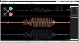
Checking the filters
With the now set filters, we do a throttle sweep testflight. Now we compare the pre- and post filtered spectral analyzer graph so see, how well the filters dampen the noise. If we missed the correct frequency range, or set the filters too low. Re-adjust the filters accordingly. Weaken them further, if it’s „too clean“, in favor of filtering latency.
Repeat that process, until you see „acceptable“ noise in the post filtered graphs.
PID Toolbox Spectral Analyzer Throttle Sweep